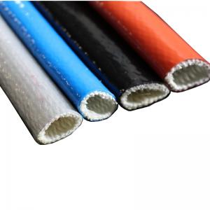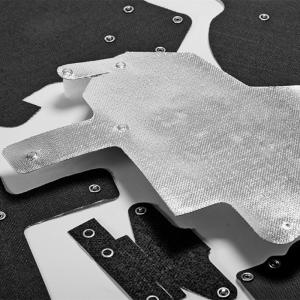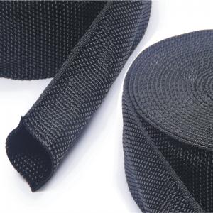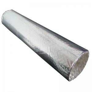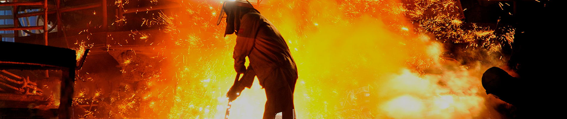
Акомпенсационный шов из тканиЭто гибкое соединение, устанавливаемое в промышленных воздуховодах для компенсации перемещений между секциями оборудования или воздуховодов. Вместо того чтобы вызывать тепловое расширение, вибрацию или изменение соосности жестких стальных конструкций, гибкий участок деформируется по мере движения системы.
Тканевые компенсаторы широко используются в системах, транспортирующих горячий воздух, отработанные газы, дымовые газы и другие газообразные технологические среды. Их гибкий элемент может состоять из тканых технических тканей, тканей с покрытием, газонепроницаемых мембран, армирующих слоев и теплоизоляции, подобранных в соответствии с фактическими условиями эксплуатации.
Поскольку гибкий элемент неметаллический, этот тип соединения также широко называютнеметаллический компенсационный шовилинеметаллический тканевый компенсационный шов.
Для ознакомления с индивидуальными проектами промышленного дизайна см. разделНеметаллический тканевый компенсационный шов BSTFLEX.
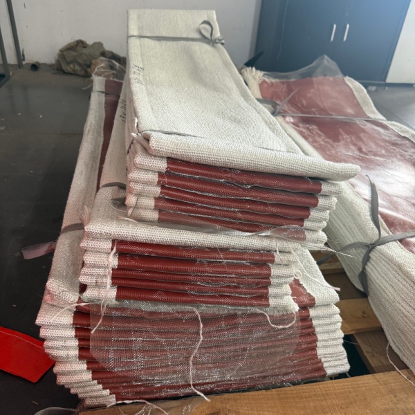
Тканевый компенсационный шов представляет собой специально разработанную гибкую секцию, расположенную между двумя относительно жесткими частями воздуховодной системы. Его назначение — обеспечить контролируемое перемещение при сохранении необходимого соединения между этими секциями.
Промышленные воздуховоды редко сохраняют свои размеры неизменными во время работы. Когда печь, котел, вытяжная система или технологический воздуховод нагреваются, окружающая металлическая конструкция расширяется. При охлаждении она снова сжимается. Вентиляторы и вращающееся оборудование также могут вызывать вибрацию, а допуски при монтаже могут создавать небольшие смещения между соседними компонентами.
Если эти движения передаются непосредственно через жесткие воздуховоды, они могут создавать дополнительные нагрузки на:
Тканевое соединение создает гибкую зону, где часть этого движения может происходить без необходимости того, чтобы вся конструкция воздуховода вела себя как жесткая сборка.
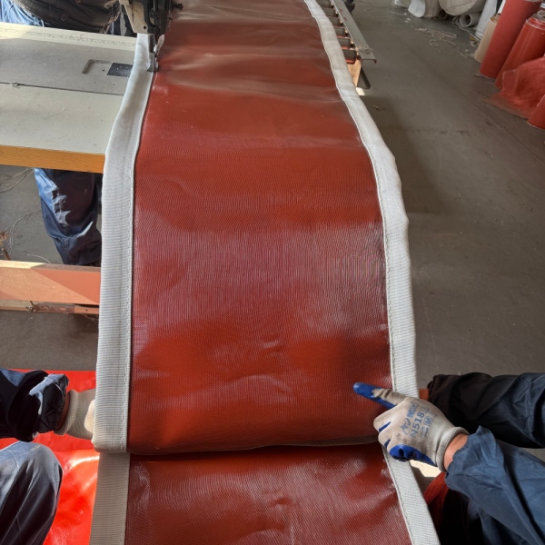
Терминнеметаллический компенсационный шовописывает гибкий элемент, а не каждый компонент в сборке целиком.
Вокруг соединения по-прежнему могут использоваться металлические рамы, зажимные планки, вкладыши или другая фурнитура. Однако секция, осуществляющая основное гибкое движение, изготавливается из ткани, эластомера, текстиля с покрытием, ламинированной мембраны или комбинации этих материалов вместо формованного металлического сильфона.
Это различие важно, поскольку тканевые и металлические компенсационные швы ведут себя по-разному.
Металлический сильфон компенсирует движение за счет изгиба формованных металлических гофр. Тканевый компенсатор использует гибкость своего текстильного или композитного пояса для изменения формы при движении воздуховода.
Для крупных промышленных воздуховодов, особенно тех, по которым транспортируются газообразные среды под относительно низким давлением, такая конструкция обеспечивает значительную свободу перемещения в компактном монтажном пространстве.
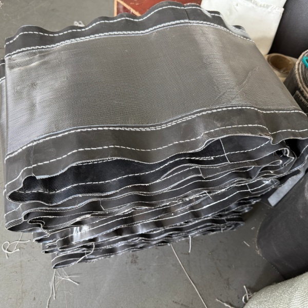
Основной принцип работы прост.
Представьте себе два участка воздуховода с горячей водой, разделенных контролируемым зазором. Гибкий тканевый элемент перекрывает этот зазор и надежно крепится по периметру каждого участка воздуховода.
Когда воздуховод нагревается и расширяется, расстояние или выравнивание между двумя секциями изменяется. Вместо того чтобы сопротивляться этому движению, как это делало бы жесткое соединение, гибкий ремень меняет свою форму.
В зависимости от конструкции, сустав может реагировать на несколько типов движений.
Осевое сжатие происходит, когда расстояние между двумя участками воздуховода уменьшается вдоль центральной линии.
Это часто происходит, когда тепловое расширение приводит к смещению одного участка воздуховода навстречу другому. Гибкий пролет сжимается или складывается контролируемым образом, чтобы компенсировать уменьшение расстояния.
Осевое растяжение представляет собой противоположное состояние. Расстояние между соединяемыми участками увеличивается вдоль продольной оси.
Тканевый элемент должен обладать достаточной геометрической формой, чтобы растягиваться без чрезмерного растяжения.
Боковое смещение происходит, когда одно соединение воздуховода смещается вбок относительно другого.
Это особенно важно в больших системах воздуховодов, где перемещение оборудования, тепловое расширение в другом направлении или геометрия установки создают смещение, а не простое сжатие или растяжение.
Угловое смещение происходит, когда две соединяемые грани перестают быть параллельными.
Гибкий ремень неравномерно деформируется по всему периметру, позволяя одной стороне сжиматься, а другой — растягиваться.
В реальных промышленных системах движение не всегда происходит только в одном направлении. Осевое, боковое и угловое смещение могут происходить одновременно.
Это одна из причинкомпенсационный шов для тканевого воздуховодаЭтот метод особенно полезен в сложных конструкциях воздуховодов. Геометрию соединения можно проектировать с учетом ожидаемой комбинации движений, а не рассматривать каждое перемещение по отдельности.
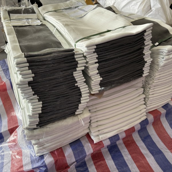
Наиболее известной причиной установки компенсационного шва является тепловое расширение, но не единственной.
Полное требование к перемещению может быть обусловлено различными условиями эксплуатации.
| Причина | Что происходит в системе? | Роль деформационного шва |
|---|---|---|
| Тепловое расширение | Металлические воздуховоды расширяются при повышении температуры. | Обеспечивает контролируемое перемещение в пространстве. |
| Термическое сжатие | Монтаж воздуховодов во время простоя или охлаждения. | Allows the system to return toward its cold position |
| Fan Vibration | Mechanical vibration is transferred from rotating equipment | Provides a flexible connection between equipment and ducting |
| Misalignment | Connecting duct faces may not be perfectly aligned | Can accommodate specified offsets within the joint design |
| Structural Movement | Supports or equipment may move relative to each other | Provides a controlled flexible section |
| Operating Cycles | Repeated heating and cooling creates cyclic movement | Accommodates repeated dimensional changes when correctly designed |
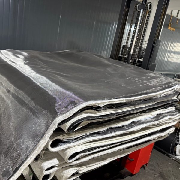
A fabric expansion joint should not be viewed simply as a piece of cloth connecting two ducts.
The flexible section is an engineered material system. Depending on service conditions, it may use a single flexible layer or several different layers, each selected for a specific function.
The outer layer forms part of the flexible envelope and may also provide resistance to weathering, environmental exposure or external mechanical conditions.
This layer helps contain the process gas. Its material must be compatible with the expected temperature, gas composition, moisture and chemical exposure.
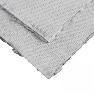
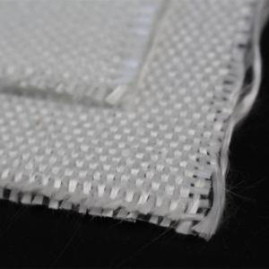
Reinforcement provides mechanical support and dimensional stability to the flexible element. Fiberglass and other technical textile constructions are commonly considered depending on temperature and mechanical requirements.
High gas temperature does not necessarily mean every layer of an expansion joint should be exposed directly to that temperature.
An insulation package can reduce heat transfer from the process side toward temperature-sensitive sealing or outer layers.
Hot gas velocity, ash, dust or abrasive particles can damage an unprotected flexible surface. Some systems therefore require an internal liner, baffle or other protection to shield the joint from direct gas flow and particulate impact.
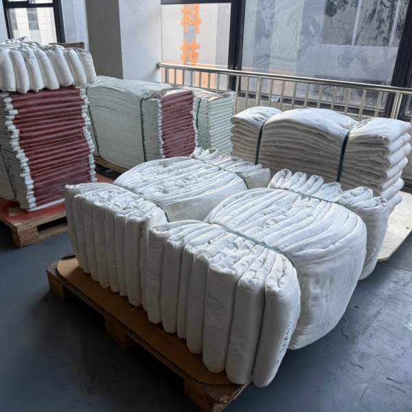
One material rarely provides every property required by a severe industrial application.
For example, a material with excellent temperature resistance may not provide the best gas sealing. A highly flexible sealing material may require reinforcement. A chemically resistant membrane may need insulation to keep its operating temperature within an acceptable range.
As a result, manyfabric expansion jointsuse a combination of materials rather than one fabric performing every function.
Typical material families include:
BSTFLEX also manufactures a broad range ofhigh temperature fabrics, allowing material construction to be evaluated according to thermal, chemical and mechanical requirements.
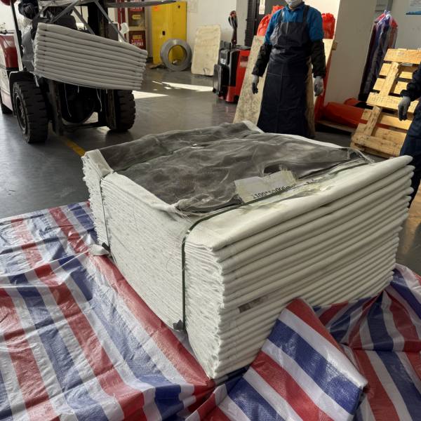
Fabric joints are mainly associated with industrial gas-handling and ducting systems rather than conventional high-pressure liquid piping.
Typical applications include the following.
Boilers, furnaces and combustion equipment can generate hot flue gases that must travel through large duct networks. These ducts experience significant dimensional change between ambient and operating temperatures.
Exhaust ducts connected to engines, industrial furnaces, thermal processing equipment or pollution-control systems may require movement compensation between hot equipment and downstream ducting.
Power plants use large gas-handling systems around boilers, fans, air-handling equipment and emission-control installations. Thermal growth and vibration can occur at multiple connection points.
Cement production combines heat, large duct dimensions, dust and continuous process operation. Flexible expansion sections may be required around kiln-related systems, fans and process ducts.
High-temperature furnaces, hot-air systems and exhaust ducts in steel and metal-processing plants can generate significant thermal movement.
Placing a flexible connection between rotating equipment and rigid ducting can help prevent all equipment movement from being transmitted directly into the surrounding duct structure.
Large ducting systems used with filtration, scrubber, flue-gas treatment and other air-pollution-control equipment often need flexible connections between process components.
Both products are intended to manage movement, but they should not be considered interchangeable simply because they share the term “expansion joint.”
| Characteristic | Fabric Expansion Joint | Metallic Bellows |
|---|---|---|
| Flexible Element | Fabric, coated textile or composite membrane | Formed metal bellows |
| Common Application | Large industrial ducts and gaseous-media systems | Industrial piping and engineered duct or process systems |
| Movement Method | Flexible belt changes geometry | Metal convolutions flex |
| Large Duct Sizes | Well suited to custom large cross-sections | Requires application-specific metallic design |
| Multidirectional Movement | Can accommodate several movement directions in one flexible section | Depends on bellows geometry and assembly design |
| Material System | Can combine several fabric, coating and insulation layers | Primarily determined by metallic alloy and bellows construction |
Pressure, temperature, process medium, movement, duct size and system design must all be considered before deciding which expansion joint technology is appropriate.
A flexible joint can help isolate vibration between connected components because its flexible element does not behave like a completely rigid metal duct section.
This is useful near fans, blowers and other equipment that produces mechanical vibration.
However, vibration should still be treated as an engineering input. Frequency, amplitude, equipment arrangement and joint geometry all influence performance. A fabric expansion joint should not be selected only because a system is described as “vibrating.”
There is no universal movement value that applies to every fabric expansion joint.
Movement capability depends on:
For this reason, axial, lateral and angular movements should be stated separately when specifying a custom expansion joint.
A request such as “50 mm total movement” is less useful than specifying how that movement occurs.
For example:
These values are examples of how movement information can be communicated, not standard ratings for every joint.
There is also no single temperature rating that defines all fabric expansion joints.
The allowable process temperature depends on the complete construction.
A high-temperature joint may be designed so that the process-side protection and insulation reduce the temperature reaching the gas-sealing membrane and external flexible layers.
Temperature selection should therefore consider:
This is why specifying only “high temperature fabric expansion joint” is insufficient for engineering selection.
A manufacturer needs more than the nominal duct dimensions to select a reliable construction.
The most useful project information includes:
| Design Information | Typical Details Required |
|---|---|
| Duct Geometry | Round, rectangular, square or special shape |
| Dimensions | Diameter or width and height |
| Face-to-Face Length | Available installation distance |
| Temperature | Normal and maximum process temperature |
| Pressure | Positive or negative operating and design pressure |
| Process Medium | Hot air, flue gas, exhaust gas or other process gas |
| Axial Movement | Compression and extension |
| Lateral Movement | Required transverse offset |
| Angular Movement | Required angular displacement |
| Chemical Conditions | Acidic, alkaline, moisture or other process exposure |
| Particulate Loading | Dust, ash or abrasive particles |
| Installation Environment | Indoor, outdoor, weather exposure or confined area |
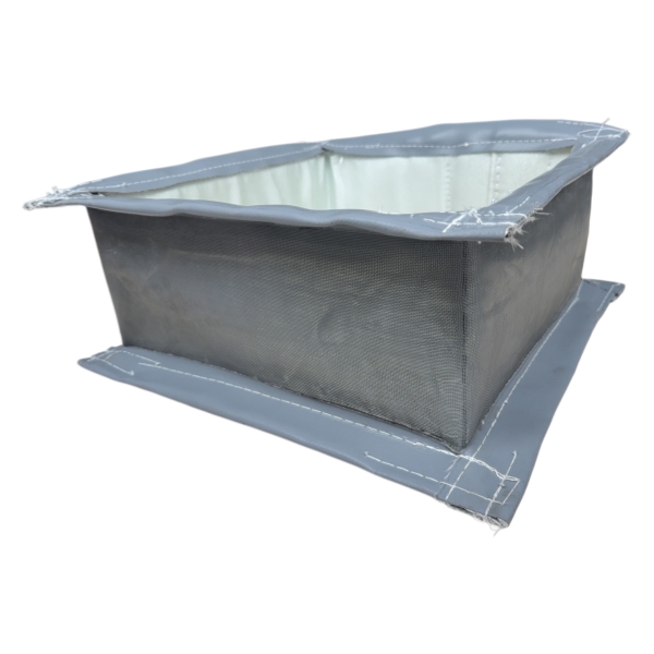
Anon metallic expansion jointshould be considered when an industrial ducting system needs flexibility and the operating conditions are suitable for a fabric-based construction.
Typical reasons include:
The final decision should always be based on actual system conditions rather than the product name alone.
Some basic constructions can be standardized, but industrialfabric expansion jointsare frequently customized.
Two ducts with the same dimensions may require completely different expansion joints if they operate at different temperatures, carry different gases or experience different movements.
Important differences may include:
This is why drawings and operating data are particularly valuable when sourcing replacement or OEM fabric expansion joints.
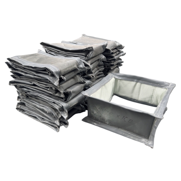
Rectangular joints are widely used on large industrial duct systems. Their corner sections require careful design because the flexible element does not deform identically along straight sides and corners.
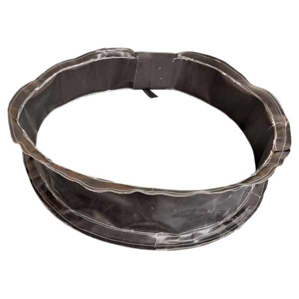
Round joints are used on circular ducting, fan connections and exhaust systems. The circumference provides a continuous attachment surface around the duct.
Square configurations are similar in principle to rectangular designs but may be required by specific duct or equipment layouts.
Transitions, non-standard dimensions and application-specific geometries can be manufactured when existing industrial equipment cannot accept a standard shape.
Expansion joint service life depends heavily on correct specification and installation.
Potential failure mechanisms include:
A damaged joint should therefore not automatically be replaced with an identical copy without understanding why the original unit failed.
For replacement projects, operating history can be as valuable as dimensional information.
In industrial ducting, the terms are often used for closely related products. A fabric expansion joint uses a flexible non-metallic fabric or composite element, so it falls within the broader non-metallic expansion joint category. The exact terminology varies by industry and construction.
It provides a flexible connection between sections of industrial ductwork so thermal expansion, contraction, lateral displacement, angular movement, vibration and specified misalignment can be accommodated without making the connection completely rigid.
Typical locations include industrial exhaust ducts, flue-gas systems, furnace and boiler ductwork, fan connections, cement plants, power-generation equipment, steel-processing facilities and air-pollution-control systems.
Yes. Depending on the design, they can accommodate axial compression, axial extension, lateral movement, angular movement and combinations of these movements.
No. Fiberglass is an important reinforcement and high-temperature textile, but complete expansion joints may combine coated fiberglass, PTFE-coated fabric, silicone-coated textiles, silica fabrics, insulation and other materials according to operating conditions.
Да, если вся система материалов спроектирована с учетом фактической температуры процесса и газовых условий. В высокотемпературных областях применения часто требуется несколько функциональных слоев и соответствующая защита между потоком горячего газа и гибким уплотнительным элементом.
Не автоматически. Тканевые и металлические компенсационные швы имеют разные характеристики по давлению, подвижности, температуре и механическим свойствам. Перед изменением технологии компенсационных швов необходимо оценить состояние системы.
Полезная информация включает ширину и высоту или диаметр воздуховода, расстояние между торцами, размеры фланца, расположение болтов, форму соединения и доступное монтажное пространство. Также важны требования к рабочей температуре, давлению, рабочей среде и перемещению.
Компания BSTFLEX разрабатываеткомпенсационные швы тканиПредназначены для промышленных воздуховодов, вытяжных систем, систем горячего воздуха и дымовых газов. Конструкция может быть адаптирована к круглым, прямоугольным, квадратным и нестандартным формам воздуховодов, а материалы выбираются в зависимости от температуры, давления, рабочей среды, перемещения и условий монтажа.
Если вы разрабатываете новую систему или заменяете существующее соединение, ознакомьтесь с информацией по следующим вопросам:Неметаллический тканевый компенсационный шов BSTFLEXНа странице товара представлены доступные варианты конструкции и индивидуальной настройки.
Для инженерной оценки пришлите размеры воздуховодов, нормальную и максимальную температуру, рабочее давление, рабочую среду, осевое и боковое перемещение, длину монтажа, количество и имеющиеся чертежи.
Запросите индивидуальный расчет стоимости компенсационного шва для ткани.

 English
 français
 Deutsch
 italiano
 español
 português
 Nederlands
 العربية
 日本語
日本語 한국의
한국의 Türkçe
 Polski
 Tiếng Việt
 slovenský
 Indonesia